Luminograms
The technique of the luminogram, especially the plotter controlled luminogram has been taking a more central
role in my work and it felt necessary to shed some light on the technique in a dedicated place.
A luminogram is similar to a photogram, as these are both camera-less analogue photography techniques.
Photograms are perhaps the better known of the two techniques, popularized by artists like Man Ray and
László Moholy-Nagy. At its core, a photogram is created by placing objects directly onto photographic paper
and exposing it to light. Think of it as creating a shadow print of real objects.
Luminograms take a more abstract approach. Instead of working with physical objects, photographers
manipulate light itself to create images. This technique explores the fundamental nature of light as both
wave and particle.
Black/white Luminograms
soon
Color Luminograms
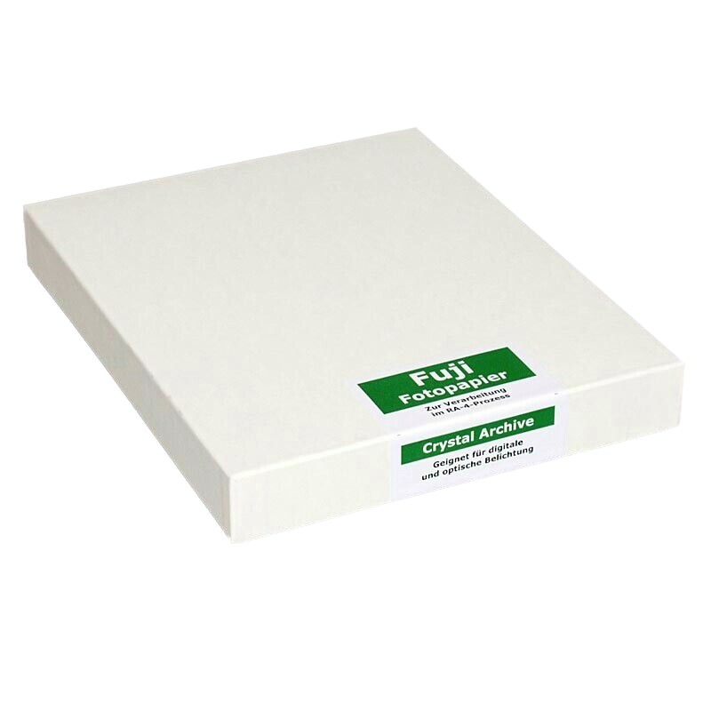
The RA-4 process is a widely used method in color photography for producing prints from color negatives. This chromogenic process involves a series of chemical reactions that develop the latent image on photographic paper into a full-color photograph. Photographic paper used in the RA-4 process comprises multiple layers, each sensitive to different colors of light: blue, green, and red. These layers contain silver halide crystals and dye couplers specific to cyan, magenta, and yellow dyes.
.jpg)
The process works like that:
1. Expose the paper via a custom rgb-led encapuslation "pen"
2. The exposed paper is immersed in a color developer containing a developing agent. This agent reduces the
exposed silver halide crystals to metallic silver. Simultaneously, the oxidized developer reacts with the
dye couplers in each layer, forming cyan, magenta, and yellow dyes in proportion to the exposure.
3. After color development, the paper undergoes a bleach-fix process that removes the metallic silver,
leaving behind only the dye image. This step ensures the final print is stable and free from residual
silver.
4. The paper is thoroughly washed to remove any remaining chemicals and then dried, resulting in a finished
luminogram.
The colors in the final luminogram emerge from the interaction between the oxidized developer and the dye
couplers during the color development stage. Each layer of the photographic paper is sensitive to a specific
color of light and contains corresponding dye couplers:
Blue-sensitive layer: Contains yellow dye couplers.
Green-sensitive layer: Contains magenta dye couplers.
Red-sensitive layer: Contains cyan dye couplers.
When exposed to light, the silver halide crystals in each layer form a latent image. During development, the
oxidized developer reacts with the dye couplers to form dyes in the areas where exposure occurred. The
combination of these cyan, magenta, and yellow dyes through subtractive color mixing reproduces the full
spectrum of colors present in the original scene. Also known as Chromogenic Photography
notes
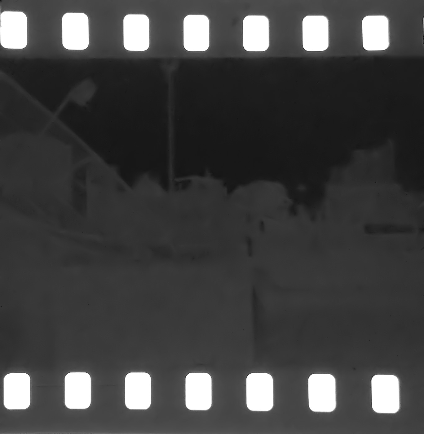
A latent image is an invisible image produced by the exposure to light of a
photosensitive material such as photographic film. [...] so the image was said to be "latent" until
the film was treated with photographic developer.
src wikipedia
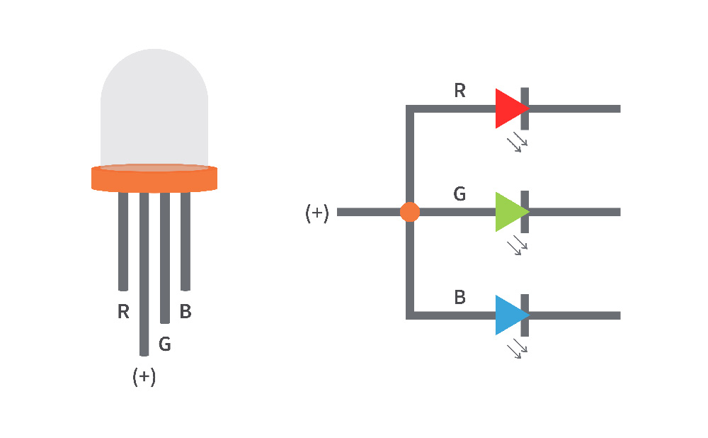
rgb led

Pulse Width Modulation, or PWM, is a technique for getting analog results with digital means. Digital control is used to create a square wave, a signal switched between on and off. This on-off pattern can simulate voltages in between the full Vcc of the board (e.g., 5 V on UNO, 3.3 V on a MKR board) and off (0 Volts) by changing the portion of the time the signal spends on versus the time that the signal spends off. The duration of "on time" is called the pulse width. To get varying analog values, you change, or modulate, that pulse width. If you repeat this on-off pattern fast enough with an LED for example, the result is as if the signal is a steady voltage between 0 and Vcc controlling the brightness of the LED. In the graphic below, the green lines represent a regular time period. This duration or period is the inverse of the PWM frequency. In other words, with Arduino's PWM frequency at about 500Hz, the green lines would measure 2 milliseconds each.

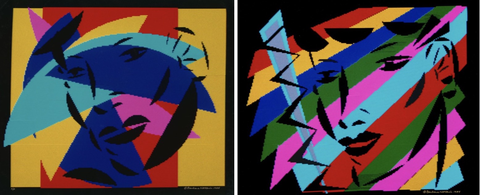
Andreas Gysin & Sidi Vanetti, Link